WelderDestiny › E-Zine Back Issues › Issue #077
The WelderDestiny Compass
Transfer Mode - Issue #077
Wednesday, July 18, 2018 / Perth Australia / By Niekie Jooste
In this edition of "The WelderDestiny Compass":
- Transfer Mode Essential Variable
- The Different Welding Transfer Modes
- Parameters Affecting Transfer Mode
- Qualified Ranges For Transfer Mode
Transfer Mode Essential Variable
We continue to explore another welding essential variable this week.
The welding transfer mode essential variable is primarily associated with the Gas Metal Arc Welding (GMAW) process. This welding process is also called the Metal Inert Gas (MIG) or Metal Active Gas (MAG) process, depending on whether an inert or active gas is used for the shielding.
Some codes also include the Flux Cored Arc Welding (FCAW) process into this, but in the case of FCAW things are not so clear. We will discuss this later in this article.
In essence, the transfer mode is a description of how the molten metal from the electrode is transferred into the weld puddle.
In this article we will look at the different welding transfer modes and their characteristics, what parameters have an influence on it, and how different codes deal with it as an essential variable.
If you would like to add your ideas to this week’s discussion, then please send me an e-mail with your ideas. Send your e-mails to: compass@welderdestiny.com
Now let's get stuck into this week’s topics...
The Different Welding Transfer Modes
There are essentially 3 different welding transfer modes for the GMAW process. They are:
- Dip transfer (Also called short circuiting transfer.)
- Globular Transfer
- Spray transfer
There is another transfer mode that is only found under somewhat extreme conditions, so we will not discuss that further in this article.
We also get a pulsed spray transfer, but this is not really a uniquely different transfer mode. It is a combination of dip and spray transfer. We will also discuss this further below.
Dip Transfer:
In dip transfer, the welding parameters are set in such a manner that the wire feeds faster than it is able to burn off in the arc. As a consequence, the wire dips into the weld puddle creating a momentary "short circuit", momentarily extinguishing the welding arc.
The short circuit results in resistance heating of the consumable electrode wire. Once the wire temperature becomes high enough, the combined heat of the wire and the weld puddle melts a small portion off the end of the wire.
The magnetic fields within the welding arc area then tends to pinch this small molten section off, leaving it in the weld puddle while reigniting the welding arc, reintroducing an arc gap.
This sequence is then repeated multiple times per second.
The important point to notice is that the molten metal is transferred to the weld puddle during the short circuiting phase.
Dip transfer is typically achieved through low energy welding parameters. This means that the weld puddle is relatively small and less fluid. This aids the welder when welding out of position, as the weld pool can be kept in position by the surface tension of the molten metal. Dip transfer is a lower deposition rate and low penetration welding mode.
Due to the low penetration characteristic, lack of fusion defects are very common when performing dip transfer GMAW. For this reason, some welding codes will only allow very small increases in base metal thickness (typically 1.1 times WPS qualification coupon thickness) when welding with dip transfer.
Spray Transfer:
In spray transfer, the welding parameters are set in such a manner that the arc gap is constantly maintained at quite a large value.This means that the molten weld metal needs to transfer across the arc gap in small droplets, as the short circuiting effect does not occur.
In the spray transfer mode (also called axial spray transfer) the melting of the consumable electrode wire is driven mainly by the heat of the welding arc. The magnetic fields within the welding arc then tends to pinch off the molten weld metal and drive it across the arc into the weld puddle in a very straight "axial" stream.
Many small droplets are transferred by this spray effect every second. These drop are typically much smaller in diameter than the welding wire.
Spray transfer is typically achieved through high energy welding parameters. This means that the weld puddle is relatively large and fluid, making it largely impossible to manipulate out of position. The main exception to this rule is that spray transfer is possible when welding aluminium alloys. Spray transfer is a high deposition rate and high penetration welding mode.
When possible, weldments are manipulated to a position that allows flat or horizontal spray transfer, as this maximizes efficiency.
Globular Transfer:
In globular transfer the welding parameters are set in such a manner that relatively large globules of molten weld metal is transferred across the arc. Typically the globules of weld metal have a larger diameter than the welding wire being used.
It is important to notice that in the globular transfer mode the arc is maintained constantly, and the short circuiting effect is not experienced.
Globular transfer is a medium to high energy welding mode. Mostly it can be used for welding out of position.
The main disadvantage of globular transfer is the greater weld spatter experienced. This not only reduces the deposition rates, but also greatly increases the cleaning costs after welding, as the spatter normally needs to be removed.
Pulsed Spray Transfer:
In pulsed spray transfer, the welding voltage and amperage is "pulsed" in such a manner that the transfer mode tends to fluctuate between dip transfer and spray transfer.
This is done to allow the welder to experience the advantages of both the dip and spray transfer modes. It allows the welder to perform better penetration welds than dip transfer, but also allows welding out of position.
Parameters Affecting Transfer Mode
The welding parameters that have an influence on the welding transfer mode are as follows:
- Power Source
- Welding Voltage
- Welding Amperage
- Shielding Gas
Power Source:
As a general rule, GMAW is performed with a Constant Voltage (CV) power source. (Click here to read more about the different power sources...)
It is possible to perform GMAW with a Constant Current (CC) power source, but then a voltage sensing wire feeder needs to be used. As most modern inverter power sources can easily change between CV and CC, the use of voltage sensing wire feeders are no longer common. For this reason we will not discuss it further in this article.
The CV power source is required for dip transfer, because it results in the great increase in amperage as the voltage reduces, due to the short circuiting effect. This very large spike in welding current is required to provide the resistance heating in an extremely short space of time. In other words, even with a wire sensing wire feeder, a CC power source cannot be used for welding in dip transfer mode.
Welding Voltage:
Many sources reference the transition between the different transfer modes in terms of the amperage. I believe it is much easier to think of the voltage as the primary driver of the different welding transfer modes. (Click here to see a more extensive discussion on welding voltage...)
Clearly, for dip transfer to occur, the voltage needs to be set low enough so that the welding arc is very short, enabling it to be easily short circuited. As the voltage increases, the arc gap becomes to large for the short circuiting effect to occur. At that point the transfer mode starts to move over to globular. Once the voltage goes high enough, in conjunction with a high welding current, the magnetic fields become great enough to result in the pinch effect that gives rise to the spray transfer mode.
The exact voltage ranges for the different transfer modes are obviously functions of the other parameters as well, but the following are good rules of thumb:
- Dip transfer below 19 V mostly, but up to 24 V.
- Globular transfer between 19 V and 28 V.
- Spray transfer from 26 V and up, but certainly above 30 V.
Welding Amperage:
As stated earlier, many sources use the amperage as the primary driver for transfer mode. As a general rule, as the amperage increases, the transfer range moves from dip to globular to spray. (Click here to see a more extensive discussion on welding current...)
There is no easy rule of thumb for relating the welding transfer mode only from the current. Rather we need to also know the welding wire diameter and the gas used. Then we can look it up on tables or graphs. As part of the welding gas discussion we will look at some curves to give the full picture.
Shielding Gas:
The type of welding shielding gas has important impacts for all welding processes, even those using fluxes rather than gas out of a cylinder. This is so because the characteristics of the welding plasma created in the welding arc is directly related to the gasses present in the plasma.
In the case of a fluxing welding process like SMAW, (stick) the flux releases gasses such as carbon dioxide and hydrogen that provide this shielding gas, leading to distinctive arc plasma properties.
In the case of GMAW, different gas mixtures result in different energies and magnetic effects within the arc plasma, which can significantly affect the transfer mode. The following rules of thumb can be used:
- At least 80% Argon is needed for a true spray transfer mode.
- For globular transfer and dip transfer in carbon steels, 100% CO2 can be used, but this does result in greater weld spatter.
To see the effect of the different welding parameters, look at the different graphs below:
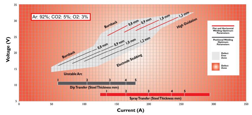 Commercial Gas For Light Steel: Note the distinct voltage ranges for the dip transfer and spray transfer modes. The globular transfer mode lies in the space between.
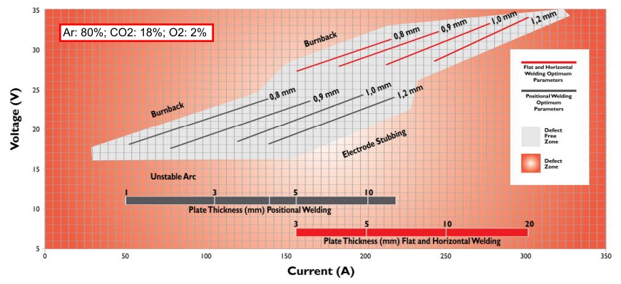 Commercial Gas For Heavy Steel: Note similar look to graph as above, but voltage ranges slightly changed.
Qualified Ranges For Transfer Mode
There are two main ways in which the welding codes deal with the welding transfer mode variable. Some codes specifically add the transfer mode as an essential variable, while other codes place tight limits on the amperage, voltage and shielding gas compositions. In this way they ensure that the same welding transfer mode is maintained for the welding procedure ranges.
Due to the lack of fusion issues associated with dip transfer welding, some codes will place tighter limits on some essential variable qualified ranges for dip transfer than the other transfer modes. Typically this would be the qualified range for the material thickness.
It is also worth noting that some codes do not treat GMAW and FCAW differently with regards welding transfer mode. This is a bit of an odd situation, because when fluxes are present, the transfer modes become much more difficult to really establish. In fact, as far as I am concerned, the FCAW transfer mode is almost always globular. I do not believe that true dip or spray transfer is possible in the presence of fluxes.
The main American pressure system welding code is ASME IX. The ASME IX welding code does not allow a change from globular, spray or pulsed spray to short-circuiting transfer or vice versa.
The Australian pressure equipment welding code is AS 3992. It deals with the welding transfer mode in pretty much the same way as ASME IX, by directly limiting the change from dip transfer to the other transfer modes or vice versa.
The Australian cross country pipeline welding code is AS 2885.2. It does not allow any change in transfer mode outside that which was used during the WPS qualification weld.
A widely used subsea pipeline code is DNV-OS-F101. It deals with the welding transfer mode in pretty much the same way as ASME IX, by directly limiting the change from dip transfer to the other transfer modes or vice versa.
In Europe, the ISO 15614-1 is a common specification used for many different product types. It deals with the welding transfer mode in pretty much the same way as ASME IX, by directly limiting the change from dip transfer to the other transfer modes or vice versa.
The American structural steel welding code is AWS D1.1. It is similar to the DNV-OS-F101 code in that it does not allow any change from the transfer mode used when welding the WPS qualification coupon.
The Australian structural steel welding code is AS1554.1. It is similar to the DNV-OS-F101 code in that it does not allow any change from the transfer mode used when welding the WPS qualification coupon.
Yours in welding
Niekie Jooste
WelderDestiny › E-Zine Back Issues › Issue #077