WelderDestiny › Welding Procedure › Welding Voltage
Welding Voltage Essential Variable
There are only a few welding parameters that directly affect the physics of the welding arc. The welding voltage is one of those parameters. For this reason it is an essential variable in one form or another in most welding codes.
The welding voltage is also an important contributor to the welding heat input. If you want to know more about the welding heat input essential variable, then please click here...
In this essay we will look at how the welding voltage is set in different welding processes, and what its effect is in different circumstances. We will also look at how many of the common welding codes deal with the welding voltage as variable.
The WelderDestiny Compass: Weekly e-zine Subscription
You can take a look at "The WelderDestiny Compass" back-issues by clicking here.
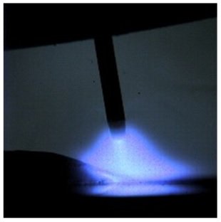 Close Up Image of Gas Metal Arc Welding (GMAW) Arc.
Explaining What The Welding Voltage Is
Discussions regarding the voltage, and how it relates to other parameters such as the amperage, can be confusing when we do not agree on what we are talking about. The concepts are somewhat different from what we are used to based on our understanding of voltages in a simple conductor.
In a simple conductor such as a wire, the change in voltage between two points is a function of the resistance of the conductor between those two points, and the amount of current flowing along the conductor between those two points. This is typically given in the equation:
V = R x I
Where: V = Voltage; R = Resistance in Ohms; I = Amperage.
Now, when we talk about the welding voltage, we are referring to the voltage that is measured across the welding arc. To get an accurate measurement of the "arc voltage", we should measure the voltage as close as possible to each side of the arc. Unfortunately this is not very practical. We therefore also end up measuring the voltage drop across the electrode (or part thereof) and across some portion of the welding leads and across some portion of the component we are welding to.
For now, let us assume that we are able to measure the voltage only across the arc, so we will initially just constrain our discussion to this. We will later add a short note on the implications of not being able to isolate our measurements only to the "arc gap".
Now, when there is an arc established in a gas, (as we do when we are performing arc welding) we have a plasma in which we have electrons moving from one side of the arc to the other, and we also have ionised gas molecules and atoms that move from the one side of the arc to the other. Their direction of movement being dependent on whether they are positively or negatively charged ions.
Each type of gas will have a characteristic "resistance" to the flow of these electrons and ions. Principally we can change this resistance by changing the length of the arc. In other words, when a welder increases the arc length, then s/he is effectively increasing the welding voltage.
All of this is complicated by the characteristics of the welding power source, which is what we will discuss next.
Power Source Influence on Welding Voltage
Generally speaking, there are two different types of welding power sources. These are "constant current" and "constant voltage" power sources. Just to confuse things, some people use the terms variable voltage instead of constant current, and variable current instead of constant voltage. Just be aware of this anomaly. In this article we will just use the terms constant current and constant voltage. They are the most common terms.
Figure 1 below shows us what the power characteristic curve looks like for a constant current power source.
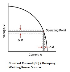 Figure 1: Characteristic curve for a Constant Current (CC) welding power source. Also sometimes called a drooping power output due to the way the curve "droops" down to the right.
This is typical of power sources used for most manual welding processes such as Gas Tungsten Arc Welding (GTAW / TIG) and Shielded Metal Arc Welding (SMAW / Stick / MMAW).
The voltage is determined by the arc length with which the Welder is welding. If we then draw a horizontal line from the voltage point on the vertical axis, we will hit the curve at a particular point. This point then shows us what the amperage will be that the power source delivers. In figure 1 above, this is the "operating point" at which the Welder is welding.
Now, we know that it is not possible for the Welder to keep exactly the same arc length the whole time. Due to simple human variability, (how steady can your hand be after all) the arc gap will continuously vary. This variation is shown by the broken horizontal lines running each side of the solid voltage line.
Due to the "drooping" nature of the power curve, we can see that even a relatively big change in voltage (change in arc length) will result in only a small change in the welding current, as measured in amps. This is why this power source is called a "constant current" power source. Even a large variation in arc length will just result in a minor change in amperage.
To vary the power output of Constant current power sources, the welder adjusts the "Amperage" control on the power source. In effect what this does is to move the entire curve to the left or right. So, for a low amperage setting, the curve moves to the left, so that for the same arc length, (Voltage) the amperage delivered by the machine is less.
Figure 2 below shows us what the power characteristic curve looks like for a constant voltage power source:
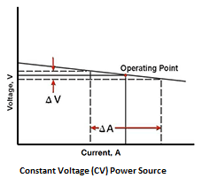 Figure 2: Characteristic curve for a constant voltage welding power source.
This is typical of power sources used for the continuous wire feeding welding processes such as Gas Metal Arc Welding, (GMAW / MIG / MAG) flux Cored Arc Welding (FCAW) and Submerged Arc Welding. (SAW)
In these welding processes, the welding voltage is set on the machine, and the current delivered by the power source is determined by the wire feed speed. When we look at Figure 2, we can see how this happens.
The power source tries to deliver the set welding voltage. This is displayed to us by the arc length. When the Welder increases the wire feed speed, then the arc gap will be shortened, in essence reducing the voltage by a small amount. This small reduction in voltage has the result of greatly increasing the amperage delivered by the power source. This increased amperage in turn burns off the wire faster, tending to again increase the arc gap, thereby pushing the voltage back to the set level.
We can see that this constant voltage power characteristic has the effect of maintaining the welding voltage within a very narrow range, by utilising big changes in the welding current. This "self correcting" mechanism is important in the continuous wire feeding processes, because it greatly reduces the probability of the wire "stubbing" into the weld puddle (causing a short circuit) if the welder does not keep the arc length totally constant.
When the voltage adjustment is made on the CV power source, the effect is to move the line in Figure 2 up or down.
For the GMAW process, the voltage is also a very important parameter in obtaining different ways in which the weld metal is transferred across the arc. This is called the transfer mode. We will look at the transfer mode essential variable in another article, but it is important for our current discussion to remember that for GMAW, the voltage has a big effect on the transfer mode.
At this point it is important to note that many modern induction power sources are capable of delivering both constant current and constant voltage characteristics. They typically have a switch that you can flick to select between Stick / TIG and GMAW / FCAW. Effectively this switch just changes the power characteristic between constant current and constant voltage.
Power Output Implications
The power output of the welding power source can be calculated as:
P = V x A
Where P = Power in Watts; V = Voltage; A = Amperage.
From this equation it is clear that an increase in Voltage, if the amperage is held constant, will result in an increase in the power that is being generated in the welding arc. This means that theoretically for a constant current (CC) power source, the welder can increase the power of the welding arc by increasing the arc length. Practically however, there is not a 100% CC output, therefore there is in fact a reduction in amperage when the voltage increases, so the total power will not necessarily increase. The exact response is therefore different for different power sources.
Increasing the arc length does however also have other implications such as the effectiveness of the gas shielding or how the metal and flux is transferred across the arc. It is therefore not possible for the Welder to change the arc length too much for the manual welding processes without introducing welding defects such as porosity or slag inclusions. An excessively long arc length will also result in an unstable arc. Too short an arc length can result in the electrode short circuiting on the work piece, resulting in "sticking" or excessive spatter or tungsten inclusions in the case of GTAW.
In other words, it is not possible to do much changing of the voltage through the arc length with a CC power source, without leading to welding quality issues, but is note-the-less an important technique for the Welder to use to achieve different weld bead results.
In the case of the welding processes that utilise a constant voltage (CV) power source, the Welder has the ability to set the welding voltage, and therefore the arc length, with the voltage control knob on the power source. As the voltage is increased for these welding processes, the energy is therefore increased for any given amperage. This change in voltage can be significant. For lower voltage dip transfer welding in GMAW, the welding is typically done at voltages below 18V. Spray transfer welding in GMAW is typically done at voltages exceeding 30V. This is a much bigger variation than is typical of the manual welding processes using CC power sources.
If you are interested in looking at this a little more deeply, click here for an interesting article on the arc length as related to the welding parameters...
Qualified Ranges For Welding Voltage
The main American pressure system welding code is ASME IX. The ASME IX welding code is one of the codes that does not directly limit the voltage for most welding processes. In other words, the voltage is a nonessential variable. ASME IX does however limit the voltage in indirect ways. For instance, the heat input is a supplementary essential variable (it needs to be taken into account when impact properties are specified) for most of the processes. The heat input is a function of the voltage, amperage and travel speed, so the voltage is controlled in an indirect way. (Click here to read more about the heat input essential variable...)
In the case of the GMAW process, the transfer mode is an essential variable. Seeing as the transfer mode is strongly correlated to the voltage, this is again an indirect voltage control.
The Australian pressure equipment welding code is AS 3992. It deals with the welding voltage in pretty much the same way as ASME IX, through indirect measures of transfer mode and heat input.
The Australian cross country pipeline welding code is AS 2885.2. It deals with the welding voltage in pretty much the same way as ASME IX, through indirect measures of transfer mode and heat input.
A widely used subsea pipeline code is DNV-OS-F101. It deals with the welding voltage in pretty much the same way as ASME IX, through indirect measures of transfer mode and heat input.
In Europe, the ISO 15614-1 is a common specification used for many different product types. It too controls the voltage indirectly through the heat input and transfer mode variables.
The American structural steel welding code is AWS D1.1. It limits the variation in voltage for the SAW, GMAW and FCAW processes to plus or minus 7% of the voltage used in the procedure qualification coupon. It does not limit the voltage for the SMAW and GTAW processes.
The Australian structural steel welding code is AS1554.1. It has the same plus minus 7% for the SAW. GMAW and FCAW processes as used in AWS D1.1, but in addition it limits the voltage for the SMAW and GTAW processes to plus minus 15% of that used in the qualification coupon.
Voltage Measuring Issues
As mentioned earlier in this article, when we are talking about the welding voltage, then ideally we want to measure it exactly across the arc only. Unfortunately this is rather impractical, as the closer we get to the welding arc, the higher the temperature, so any probe trying to attach at that point will just melt. Any probe attached close to the arc will also get in the way of the Welder.
As a result, it is only practical to measure the voltage at points somewhat remote from the welding arc.
Most modern welding power sources will have a voltage meter included. In addition to the voltage drop across the arc, this meter is also measuring the voltage drops across both the welding leads, (electrode cable and ground clamp cable) the electrode holder, the electrode and the work piece.
As long as the welding leads are relatively short, this voltage reading is not too far off, but for long welding cables, this reading will be significantly higher than the real voltage experienced across the arc.
Due to the length restrictions inherent with the feeding tubes of the typical GMAW and FCAW processes, the voltage readings on these machines can usually be relied upon. In the case of the SMAW and GTAW processes, we normally need to try to get closer to the electrode holder and work piece to get good consistent readings.
An external volt meter that you can connect close to the electrode holder and work piece is therefore important to obtain good information and consistent control between different welding set-ups for these welding processes.
WelderDestiny › Welding Procedure › Welding Voltage
The WelderDestiny Compass: Weekly e-zine Subscription
You can take a look at "The WelderDestiny Compass" back-issues by clicking here.