WelderDestiny › Welding Procedure › Base Metal Thickness
Base Metal Thickness Essential Variable
Essentially all the different welding codes have the base metal thickness as an essential variable. The main reason for this is that the thicker a metal, the quicker it is able to remove heat from the welding arc. Another way of putting this is that the "heat sink" effect of the base metal increases with increasing thickness.
This change in the heat sink effect for different thicknesses of material has a number of different implications while we are welding. In this article, we will look at some of those implications.
The WelderDestiny Compass: Weekly e-zine Subscription
You can take a look at "The WelderDestiny Compass" back-issues by clicking here.
Fusion Implications
If the thermal energy introduced by the welding arc is rapidly removed from the weld, then the amount of base metal melting that occurs will decrease. Under particularly adverse conditions, the heat from the arc can be removed out of the welding area so rapidly that no melting of the base metal occurs. We then get a lack of fusion defect being created.
This is particularly evident in welding processes where the heat input into the weld is very low. An example of this is the Gas Metal Arc Welding (GMAW) process when using "dip transfer". (Also called short circuiting transfer.) When welding with the dip transfer mode of GMAW, a lot of the heat goes into resistance heating of the wire, and not into the arc. This means that it is quite easy to melt the welding wire without actually melting the base metal.
For this reason, most codes limit the maximum base metal thickness qualified to 1.1 times the thickness of the qualification coupon when using the dip transfer mode for the GMAW process.
Lack of fusion is also often found when welding alloys with high thermal conductivity such as copper. This can be seen in the figure below.
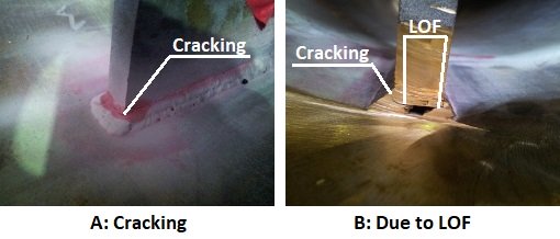 Cracking found externally as seen in photo "A". This was due to lack of fusion (LOF) in the root of the weld, as seen in photo "B".
Cooling Rate Implications
During fusion welding, the weld metal and Heat Affected Zone (HAZ) of the base metal next to the weld, undergo phase transformations and other changes to the microstructure. As the base metal thickness increases, the cooling rate of the weld and HAZ also increases.
The most obvious phase transformation is a change from a liquid (molten) metal to a solid. During this process, there is a process whereby the molten metal starts to nucleate solid "grains" of crystal, and then these nuclei start to grow, until these grains touch each other. At that point, all the liquid metal will have turned to solid. In other words, solidification is a process of crystal nucleation and growth.
The faster this process occurs, the more "grains" there are in the solidified weld. At the same time, the more grains there are, the smaller these grains need to be. In other words, the faster the solidification process, the finer the final grain structure of the weld metal.
A fine grain structure has a very pronounced effect on the strength and toughness properties of a weld. Grain refinement is one of the only ways to increase the strength of a metal while also increasing the toughness properties.
In the area next to the weld metal, the HAZ, most alloys will also experience phase transformations. These transformations are however solid state transformations. As an example, in the case of ordinary carbon steels, the steel typically changes from a ferrite phase to an austenite phase while heating up, and then the reverse happens when it cools down again.
If the cooling rate is quite rapid, then the transformation from austenite back to ferrite can be hampered, because this transformation is dependent on diffusion taking place within the metal. When there is not enough time for the necessary diffusion to take place, then the steel will transform to some intermediate "meta-stable" structure such as martensite.
The mechanical properties of these meta-stable phases are significantly different from that of the "equilibrium" phases that would form under lower cooling rates. In the case of martensite, it is a hard and brittle material. It is useful for abrasive wear applications such as bucket teeth for earth moving equipment, but it is not good for most structural applications. Luckily we can temper the martensite to form a really good material. To learn more about post weld heat treatments, click here...
While a metal is heated to high temperatures, there are also other transformations that happen to the microstructure of the metal. In particular, at high temperatures, large grains tend to grow at the expense of smaller grains. The nett result is that a material that spends a long time at high temperature results in a courser grains structure than when the material spends less time at elevated temperatures.
As stated earlier, this grain growth results in a change of the mechanical properties. In particular, a reduction in the strength and toughness, while improving the ductility and creep properties.
In short, during welding, a thin material cools down slower than a thick material, resulting in a coarser grain structure and less meta-stable phases being formed for the thin material.
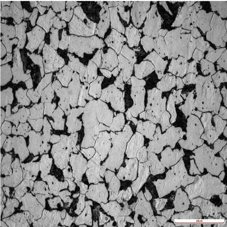 Equilibrium Microstructure: Ferrite (light) and Pearlite (dark) microstructure in a carbon steel. Equilibrium Microstructure: Ferrite (light) and Pearlite (dark) microstructure in a carbon steel. |
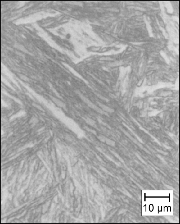 Quenched Microstructure: Martensite microstructure due to high cooling rate. Quenched Microstructure: Martensite microstructure due to high cooling rate. |
Dilution Effects In Weld Overlay
Due to the more rapid removal of heat for a greater base metal thickness, the result is that there is a steeper temperature gradient from the molten metal to the "cold" base metal. This steeper temperature gradient means that the amount of base metal being melted is less than when the base metal is thinner.
When less base metal is being melted, then the percentage of base metal being added to the filler metal is less. In welding terminology we say that there is a lower dilution of the filler metal by the base metal.
This dilution effect is very important in any circumstance where the welding consumable has a significantly different chemical composition from that of the base metal. This is very typical when performing weld overlays. A typical weld overlay may be the deposition of a type 316 stainless steel onto a carbon steel base metal.
The greater the dilution of the welding consumable during weld overlays, the more layers of weld metal may be required to achieve the required final chemical composition of the weld overlay surface.
For this reason, the base metal thickness is an important essential variable when performing weld overlay, because the thicker the base metal, typically the less the dilution will be.
In the case of weld overlay cladding, the welding codes do not allow a significant reduction in base metal thickness compared to the coupon thickness used during the procedure qualification process. There is however an "upper limit" above which the decreased dilution effect tends to stop playing such a big role. In most of the welding codes dealing with weld overlay cladding, this limit is set at 25mm. (1 Inch)
In other words, a weld overlay cladding performed on a 60mm thick coupon can be used on production base metals of 25mm and thicker.
Measuring Base Metal Thickness
As mentioned previously, the main influence of the base metal thickness is tied to the quenching effect. Different weld geometries do however result in different amounts of this quenching effect. In the case of a butt weld, the heat is drawn out of the weld joint in two directions. (See left hand image below.) In the case of a fillet weld configuration, the heat is drawn out in three directions. (See right hand image below.)
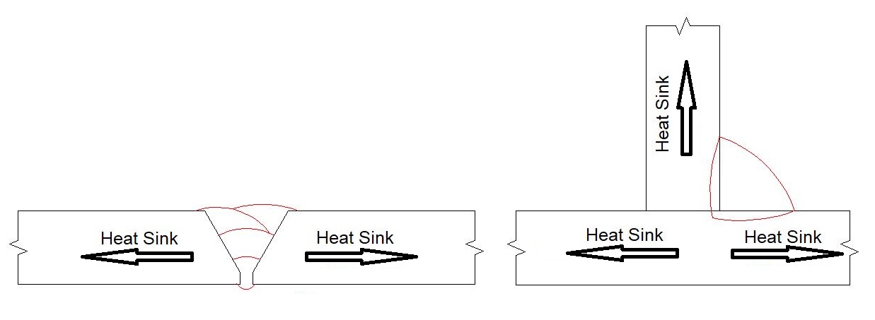 Geometry Heat Sink Effect: The butt weld configuration has 2 heat paths, while the fillet weld configuration has 3 heat paths.
Different welding codes deal with this weld configuration effect in different ways. Some of the structural welding codes, such as AS 1554.1 , uses the concept of a "combined thickness". For a material thickness of "T", for a butt weld configuration, the combined thickness is 2T, because there are two directions in which the heat can be conducted away. For a fillet weld configuration, the combined thickness is 3T, because there are three directions in which the heat can be conducted away..
ASME IX does not really deal with this effect in a satisfactory way. It merely looks at the thickness of the material being welded as a single value. As an example, two 12mm thick plates being welded in a butt configuration will have a material thickness of 12mm. Two 12mm thick plates being welded in a fillet weld configuration will also have a material thickness of 12mm.
AS3992 deals with this by taking the total thickness of all the heat paths, and then dividing by the number of heat paths, to describe the material thickness in a single number. In this way, AS3992 takes account of the weld configuration while still using only a single number for material thickness.
The table below is an extract from AS3992, showing an example of how they define the material thickness. Obviously they have a number of different sketches for the different typical weld configurations. I have only included a few, for illustrative purposes.
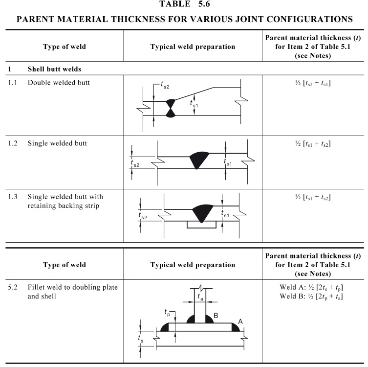 Extract From AS3992: Showing an extract of Table 5.6. These are examples of how the material thickness is defined for different weld configurations.
Qualified Ranges For Base Metal Thickness
Every welding code will deal with the base metal thickness essential variable differently, so there is no single qualified range. We will however discuss the typical approach that different welding codes take to this essential variable.
Most welding codes have an upper qualified base metal thickness that is twice the thickness of the qualification coupon. However, as we mentioned previously in the section on dilution effects in weld overlay, once the base metal thickness goes above a certain value, then this heat sink effect tends to stop increasing much. Many welding codes therefore allow the upper qualified base metal thickness to become almost unlimited if the coupon thickness is above this specific thickness.
In the case of the ASME IX welding code, if the base metal thickness of the qualification coupon was greater than 38mm, then the maximum thickness qualified is 200mm. The Australian pressure equipment code AS3992 has a very similar approach.
In the case of the AWS D1.1 structural steel code, a coupon thickness above 25mm base metal thickness qualifies for an unlimited upper thickness during production welding.
The lower thickness qualified varies between different welding codes, but a typical approach is either a half the coupon thickness, or a stepped lower limit based on the coupon thickness.
The Australian structural steel code AS 1554.1 limits the lower thickness to half the coupon thickness. The American structural steel code AWS D1.1, limits the lower thickness to 3mm for plates, regardless of the thickness of the test coupon. It is instructive to note that the scope of AWS D1.1 is limited to steel plates thicker than 3mm, so there is no need to deal with thinner materials.
ASME IX and AS 3992 give a lower limit of 1.5mm for test coupons up to 10mm thick, and a lower limit of 5mm for a test coupon thicker than 10mm.
There is a complication in that the lower thickness is often different when impact test applications are being considered. This is because of the effect of grain growth. As mentioned previously, when the cooling rate is lower due to a lower quenching effect of thinner materials, then there can potentially be a greater amount of grain growth within the weld metal and HAZ. A coarse grain structure will result in a material with less toughness than a fine grained material. The lower thickness is therefore more stringently controlled for impact test applications.
For ASME IX and AS3992, if the coupon is thicker than 16mm, then the minimum thickness qualified is 15mm. AWS D1.1 also takes a similar approach.
Base Metal Thickness Essential Variable Summary
The main effect of the base material thickness is that as the thickness increases, so the speed at which heat is removed from the weld increases. This can lead to different amounts of fusion, as well as different microstructures within the weld and heat affected zone.
Different welding codes define different qualified ranges, based on the base metal thickness essential variable. This is further complicated by the fact that the thickness range qualified will be different when impact properties are important for the particular component being welded.
Always make sure that you check the relevant welding code for the qualified range.
WelderDestiny › Welding Procedure › Base Metal Thickness
The WelderDestiny Compass: Weekly e-zine Subscription
You can take a look at "The WelderDestiny Compass" back-issues by clicking here.