| Back to Back Issues Page |
 |
|
The WelderDestiny Compass #056 - Welding Voltage February 21, 2018 |
Wednesday, February 21, 2018 / Perth Australia / By Niekie Jooste You can also read this e-zine on the WelderDestiny website by clicking here... 
Welding Voltage - Issue #056In this edition of "The WelderDestiny Compass":
Talking WeldingIt has been a while since we got into a hard core welding topic, so I thought that we should just mix it up a little and go hard core today. Next week we can again take up our quest of trying to prepare ourselves for the world of the decentralized autonomous organization.The welding voltage seems like a very simple concept, but there a few tricky bits that tend to trip some people up. We should get the voltage concept firmly under our belts if we are to better understand the finer points of arc welding. The voltage is also an important contributor to the welding heat input welding variable. Today we look at how the "arc voltage" is different from the voltage concept used in most electrical conductors and circuits, what the power source influence is on the welding voltage, and what the power output implications are of varying the voltage. If you would like to add your ideas to this week’s discussion, then please send me an e-mail with your ideas, (Send your e-mails to: compass@welderdestiny.com) or add a contribution directly into the comments form on the bottom of the e-zine page on the WelderDestiny website. Click here to add your contribution directly to the WelderDestiny website... Now let's get stuck into this week’s topics... Understanding Voltage In WeldingDiscussions regarding the voltage, and how it relates to other parameters such as the amperage, can be confusing when we do not agree on what we are talking about. The concepts are somewhat different from what we are used to based on our understanding of voltages in a simple conductor.In a simple conductor such as a wire, the change in voltage between two points is a function of the resistance of the conductor between those two points, and the amount of current flowing along the conductor between those two points. This is typically given in the equation: V = R x I Where: V = Voltage; R = Resistance in Ohms; I = Amperage. Now, when we talk about the welding voltage, we are referring to the voltage that is measured across the welding arc. To get an accurate measurement of the "arc voltage", we should measure the voltage as close as possible to each side of the arc. Unfortunately this is not very practical. We therefore also end up measuring the voltage drop across the electrode (or part thereof) and across some portion of the welding leads and across some portion of the component we are welding to. For now, let us assume that we are able to measure the voltage only across the arc, so we will initially just constrain our discussion to this. Now, when there is an arc established in a gas, (as we do when we are performing arc welding) we have a plasma in which we have electrons moving from one side of the arc to the other, and we also have ionised gas molecules and atoms that move from the one side of the arc to the other. Their direction of movement being dependent on whether they are positively or negatively charged ions. Each type of plasma will have a characteristic "resistance" to the flow of these electrons and ions. Principally we can change this resistance by changing the length of the arc. In other words, when a welder increases the arc length, then s/he is effectively increasing the welding voltage. All of this is complicated by the characteristics of the welding power source, which is what we will discuss next. Role Of The Power SourceGenerally speaking, there are two different types of welding power sources. These are "constant current" and "constant voltage" power sources. Just to confuse things, some people use the terms variable voltage instead of constant current, and variable current instead of constant voltage. Just be aware of this anomaly. In this article we will just use the terms constant current and constant voltage. They are the most common terms.Figure 1 below shows us what the power characteristic curve looks like for a constant current power source.
This is typical of power sources used for most manual welding processes such as Gas Tungsten Arc Welding (GTAW / TIG) and Shielded Metal Arc Welding (SMAW / Stick / MMAW). The voltage is determined by the arc length with which the Welder is welding. If we then draw a horizontal line from the voltage point on the vertical axis, we will hit the curve at a particular point. This point then shows us what the amperage will be that the power source delivers. In figure 1 above, this is the "operating point" at which the Welder is welding. Now, we know that it is not possible for the Welder to keep exactly the same arc length the whole time. Due to simple human variability, (how steady can your hand be after all) the arc gap will continuously vary. This variation is shown by the broken horizontal lines running each side of the solid voltage line. Due to the "drooping" nature of the power curve, we can see that even a relatively big change in voltage (change in arc length) will result in only a small change in the welding current, as measured in amps. This is why this power source is called a "constant current" power source. Even a large variation in arc length will just result in a minor change in amperage. To vary the power output of Constant current power sources, the welder adjusts the "Amperage" control on the power source. In effect what this does is to move the entire curve to the left or right. So, for a low amperage setting, the curve moves to the left, so that for the same arc length, (Voltage) the amperage delivered by the machine is less. Figure 2 below shows us what the power characteristic curve looks like for a constant voltage power source:
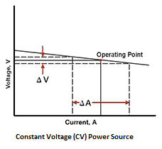
This is typical of power sources used for the continuous wire feeding welding processes such as Gas Metal Arc Welding, (GMAW / MIG / MAG) flux Cored Arc Welding (FCAW) and Submerged Arc Welding. (SAW) In these welding processes, the welding voltage is set on the machine, and the current delivered by the power source is determined by the wire feed speed. When we look at Figure 2, we can see how this happens. The power source tries to deliver the set welding voltage. This is displayed to us by the arc length. When the Welder increases the wire feed speed, then the arc gap will be shortened, in essence reducing the voltage by a small amount. This small reduction in voltage has the result of greatly increasing the amperage delivered by the power source. This increased amperage in turn burns off the wire faster, tending to again increase the arc gap, thereby pushing the voltage back to the set level. We can see that this constant voltage power characteristic has the effect of maintaining the welding voltage within a very narrow range, by utilising big changes in the welding current. This "self correcting" mechanism is important in the continuous wire feeding processes, because it greatly reduces the probability of the wire "stubbing" into the weld puddle (causing a short circuit) if the welder does not keep the arc length totally constant. When the voltage adjustment is made on the CV power source, the effect is to move the line in Figure 2 up or down. For the GMAW process, the voltage is also a very important parameter in obtaining different ways in which the weld metal is transferred across the arc. This is called the transfer mode. We will look at the transfer mode essential variable in another article, but it is important for our current discussion to remember that for GMAW, the voltage has a big effect on the transfer mode. At this point it is important to note that many modern induction power sources are capable of delivering both constant current and constant voltage characteristics. They typically have a switch that you can flick to select between Stick / TIG and GMAW / FCAW. Effectively this switch just changes the power characteristic between constant current and constant voltage. Power Output ImplicationsThe power output of the welding power source can be calculated as:P = V x A Where P = Power in Watts; V = Voltage; A = Amperage. From this equation it is clear that an increase in Voltage, if the amperage is held constant, will result in an increase in the power that is being generated in the welding arc. This means that theoretically for a constant current (CC) power source, the welder can increase the power of the welding arc by increasing the arc length. Practically however, there is not a 100% CC output, therefore there is in fact a reduction in amperage when the voltage increases, so the total power will not necessarily increase. The exact response is therefore different for different power sources. Increasing the arc length does however also have other implications such as the effectiveness of the gas shielding or how the metal and flux is transferred across the arc. It is therefore not possible for the Welder to change the arc length too much for the manual welding processes without introducing welding defects such as porosity or slag inclusions. An excessively long arc length will also result in an unstable arc. Too short an arc length can result in the electrode short circuiting on the work piece, resulting in "sticking" or excessive spatter or tungsten inclusions in the case of GTAW. In other words, it is not possible to do much changing of the voltage through the arc length with a CC power source, without leading to welding quality issues, but is none-the-less an important technique for the Welder to use to achieve different weld bead results. In the case of the welding processes that utilise a constant voltage (CV) power source, the Welder has the ability to set the welding voltage, and therefore the arc length, with the voltage control knob on the power source. As the voltage is increased for these welding processes, the energy is therefore increased for any given amperage. This change in voltage can be significant. For lower voltage dip transfer welding in GMAW, the welding is typically done at voltages below 18V. Spray transfer welding in GMAW is typically done at voltages exceeding 30V. This is a much bigger variation than is typical of the manual welding processes using CC power sources. If you want to read a little more about the welding voltage welding parameter, then please click here...
Niekie Jooste P.S. Are there issues surrounding the welding voltage that you find confusing? Do you have some insights regarding the welding voltage variable that others would find useful? Please share your stories, opinions and insights regarding today's topic, directly on the e-zine page on the WelderDestiny website. Click here to add your contribution directly to the WelderDestiny website... P.P.S If you know anybody that you believe could benefit from The WelderDestiny Compass, please forward it to them. If this e-zine was forwarded to you, and you are interested in receiving our future editions, please visit the WelderDestiny.com website and enter your e-mail details into the subscription box. It is a big red box on the home page, so you can't really miss it. - I hope! Click here for the best version of The WelderDestiny Compass back-issues... |
| Back to Back Issues Page |
 welding power source. Also sometimes called a drooping power output due to the way the curve \"droops\" down to the right.")